|
|
Home | Audio | DIY | Guitar | iPods | Music | Brain/Problem Solving | Links| Site Map
This work is licensed under a Creative Commons License.
Auto Shape Objects
Auto Shape objects are created as object groups. Unlike other object groups, however, selected Auto Shapes show diamond-shaped control points in addition to object group handles. Because each control point is associated with a particular visual property of the shape, dragging a control point alters only the associated visual property, described next.
Most control points include tooltips that describe how they affect the Auto Shape object. Move the pointer over a control point to see the tooltip. You can edit the following Auto Shape object attributes:
- Arrow: An object group that appears as a simple arrow. Using control points, you can adjust the arrowhead flare, tail length and width, and tip length.
- Beveled Rectangle: An object group that appears as a rectangle with beveled corners. Using control points or the Auto Shape Properties panel, you can edit the amount of bevel for all corners together or change the bevel of individual corners.
- Chamfer Rectangle: An object group that appears as a rectangle with chamfers (corners that are rounded to the inside of the rectangle). You can edit the chamfer radius of all corners together or change the chamfer radius of individual corners.
- Connector Line: An object group that appears as a three-segment connector line, such as those connecting elements in a flowchart or organizational chart. Using control points or the Auto Shape Properties panel, you can edit the end points for the first and third sections of the connector line, as well as the location of the second section, which connects the first and last sections.
- Doughnut: An object group that appears as a filled ring. Using control points or the Auto Shape Properties panel, you can adjust the inner perimeter or split the shape into pieces.
- L-Shape: An object group that appears as a right-angled corner shape. Using control points or the Auto Shape Properties panel, you can edit the length and width of the horizontal and vertical sections, as well as the curvature of the corner.
- Pie: An object group that appears as a pie chart. Using control points or the Auto Shape Properties panel, you can split the shape into pieces.
- Smart Polygon: An object group that appears as an equilateral polygon with three to 25 sides. Using control points or the Auto Shape Properties panel, you can resize and rotate, add or remove segments, increase or decrease the number of sides, or add an inner polygon to the shape.
- Rounded Rectangle: An object group that appears as a rectangle with rounded corners. Using control points or the Auto Shape Properties panel, you can edit the roundness of all corners together or change the roundness of individual corners.
- Spiral: An object group that appears as an open spiral. Using control points or the Auto Shape Properties panel, you can edit the number of spiral rotations, as well as determine whether the spiral is open or closed.
- Star: An object group that appears as a star with any number of points from three to 25. Using control points or the Auto Shape Properties panel, you can add or remove points, as well as adjust the inner and outer angles of the points.
- Add Shadow: An object group that adds a shadow beneath the selected vector object based on the dimensions of that object. This shadow is actually an Auto Shape and, like all Auto Shapes, contains control points that you can use to manipulate its appearance. For example, you can Shift-drag the Direction control point to constrain its movement to a 45-degree angle. Clicking the Direction control point resets the shadow to its original shape. You apply this Auto Shape by selecting Commands > Creative > Add Shadow.
The following sections describe how to change Auto Shape properties from the panel. For most shapes, simply entering a new value into a text box and pressing Tab or Enter applies it to the current shape. Some shapes have check boxes and buttons. Pressing these applies the changes immediately.
Note: When you click anywhere inside a SWF command panel in Fireworks (such as the Align, Auto Shape Properties, Image Editing, and Special Characters panels), the panel gets the focus and all subsequent key strokes are captured by the panel. As long as the panel has the focus, Fireworks shortcut keys will not work. In order to use Fireworks shortcut keys again, first click back inside Fireworks (that is, anywhere outside the panel).
Auto Shape Properties Panel
Figure 1 shows the default appearance of the Auto Shape Properties panel.
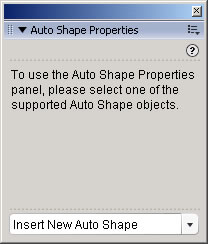
Figure 1. Default appearance of the Auto Shape Properties panel
If you have exactly one valid Auto Shape selected on the canvas, you will see a specific set of properties for that shape, as shown in the following sections. The following is a list of conditions under which this default panel will be shown:
- No active document is open
- No active selection exists on canvas
- No valid selection exists on canvas
- Two or more objects (valid or otherwise) are selected
Only Auto Shape object tools included in the shipping version of Fireworks 8 are considered valid. Any previous versions (those used in Fireworks MX 2004) and those in the Shapes tab of the Assets panel are ignored by the Auto Shapes Properties panel.
Using the pop-up menu at the bottom of the panel inserts a new Auto Shape object in the middle of the canvas.
Auto Shape Types
Following are the types of Auto Shapes you can insert into your graphics.
Arrow

Figure 2. Arrow properties (left) and corresponding parts (right)
- Width: distance between the left-most edge and base of the arrow tip
- Height: distance between the top and bottom edges of the base of the arrow
- Thickness: thickness of the base of the arrow
- Roundness: radius of the corner
- Arrow Width: distance between the two arrow tails
- Arrow Length: length of the arrow tails
- Tip Length: length of the arrow tip
Rectangle (Beveled, Chamfer, and Rounded)
Figure 3. Rectangle properties
The Rectangle properties (see Figure 3) are as follows:
- W: Width of the rectangle
- H: Height of the rectangle
Clicking the lock icon locks/unlocks the corner types and radii. If the corner types and/or their radii are different (that is, unlocked) and if you click the lock icon, the top-left corner properties are used for the remaining corners. Unlocking makes no visible difference.
Clicking a corner type button rotates through all three corner types.
If the corners are locked, entering a new value for any of the four corner radii or clicking any one of the four buttons applies the change to all four corners.
Connector Line


Figure 4. Connector Line properties (left) and example of a connector line (right)
The Connector Line properties (see Figure 4) are as follows:
- Offset: Distance between one end of the connector line and vertical/horizontal line between the two ends
- Corner: Corner radius
- Height/Width: Height/width of the connector line
A connector line can take one of two forms: horizontal (default) or vertical. When in horizontal mode, you can specify its height numerically. Similarly, when in vertical mode, you can specify its width numerically.
Each end of the Connector Line shape now automatically snaps to an object's side when you release it over an object.
The "1" and "2" in Figure 4 refer to the two ends of the connector line. To find out which one is which, simply rollover one of them; the tooltip indicates which end it is.
Doughnut

Figure 5. Doughnut properties
The Doughnut properties (see Figure 5) are as follows:
- Segments: Each value in the Segments field indicates the angle of each control point around the circumference
- Outer Radius: Outer radius of the doughnut
- Inner Radius: Inner radius of the doughnut
L-Shape
Figure 6. L-Shape properties
The L-Shape (see Figure 6) is a variant of the Arrow shape (an Arrow shape without the arrow tip). All the properties are identical to those used by the Arrow shape.
Pie
Figure 7. Pie properties
The Pie shape (see Figure 7) is a variant of the Doughnut shape (a Doughnut shape without the inner radius). All the properties are identical to those used by the Doughnut shape.
Smart Polygon
Figure 8. Smart Polygon properties
The Smart Polygon properties (see Figure 8) are as follows:
- Points: Total number of points
- Sides: Number of segments (up to the number of points)
- Outer Radius: Outer radius of the polygon
- Inner Radius: Inner radius of the polygon
- Rotation: Number of degrees by which to rotate the polygon
- Split: When checked (default), the polygon is split into separate segments; otherwise the polygon is drawn as a single closed path
Spiral

Figure 9. Spiral properties (left) and example of a spiral (right)
The Spiral properties (see Figure 9) are as follows:
- Radius: Radius of the spiral, as shown by the red line; spiral tightness is adjusted manually by using the appropriate control point
- Clockwise: When checked (default), a clockwise spiral is drawn; otherwise an anti-clockwise spiral is drawn
- Close Spiral: When checked, a closed spiral is drawn; otherwise an open spiral is drawn (default)
Star

Figure 10. Star properties
The Star properties (see Figure 10) are as follows:
- Points: Number of points
- Radius 1/2: Distance from the center of the star; these properties determine the sizes of the points
- Roundness 1/2: Distance from the center of the star; these properties determine the roundness (or the sharpness) of the points. Certain combinations of the properties can result in interesting shapes that do not resemble a simple star.
Addendum: Shadow
Unlike the other Auto Shapes described in this article, you cannot insert a shadow by selecting the Insert New Auto Shape pop-up menu in the Auto Shape Properties panel. You can insert a shadow only by selecting Commands > Creative > Add Shadow. However, once you add the shadow, you can access its properties in the Auto Shape Properties panel (see Figure 1).
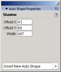
Figure 11. Shadow properties
The Shadow properties are as follows:
- Offset X: Shadow offset along the x-axis
- Offset Y: Shadow offset along the y-axis; a negative value means that the shadow is above the base of the shape (default)
- Width: Width of the shadow; adjust this property to simulate a perspective shadow
Figure 12 shows an example of a perspective shadow.
Figure 12. Example of a shadow
Home | Audio | DIY | Guitar | iPods | Music | Links | Site Map | Contact
![]()