|
|
Home | Audio | DIY | Guitar | iPods | Music | Brain/Problem Solving | Links| Site Map
This work is licensed under a Creative Commons License.
Replacing a SMD Electrolytic Capacitor
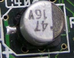
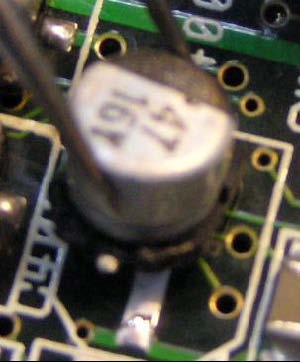
In this example, I'll be replacing C407, a 47µF 16V electrolytic capacitor in the audio power supply section of an A4000D. This capacitor, along with others in and around the audio section can develop problems where they leak corrosive electrolyte onto the circuit board. Refer to the audio repair section for more detailed information on this.
Note: There are other guides on the Internet that say to remove SMD electrolytics by "twisting" them off of the PCB using pliers. This is NOT the corec way to do it, and attempting this method is likely to result in major damage such as lifting the circuit board pads and tracks.
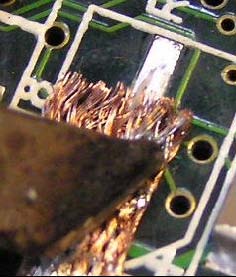
1. If you are replacing a capacitor which has leaked electrolyte, you'll see it's soldered legs are dirty/dark grey/black in colour instead of having the usual smooth, shiny appearance solder joints should have. This corrosion makes it more difficult to work on equipment, because the surface of soldered joints becomes corroded/oxidised, which makes them difficult to heat with a soldering iron. Fortunately repair using a SMD hot air tool is still fairly simple. Firstly, you will need to clean the worst of the corrosion away first using some cleaning alcohol and perhaps a fibreglass pen/brush.
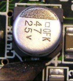
The capacitor shown below demonstrates what a clean joint should look like:
2. Next apply a little SMD flux to the legs of the capacitor you're going to remove. This makes the solder a bit easier to work with.
3. Fit a small or medium (2-6mm inside diameter) single tube nozzle to the hot air rework tool. Set the heat to medium-low and the air speed to low. You can see below I've used a heat setting of 3 and an air speed of Switch the tool on and leave it to heat up for about a minute.
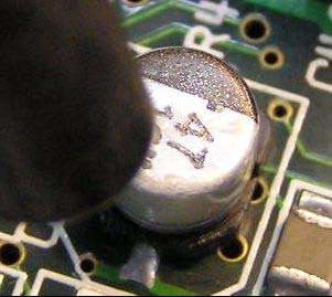
4. Hold the hot air tool in your left hand (if you are right handed). Position tip of the tool's nozzle about 10cm above the board and gently pre-heat the area for a few seconds, this reduces stress on the circuit board and surrounding components. Now hold the tip of the nozzle about 2cm above the capacitor we're removing. Move the nozzle about from side to side, heating both of the joints together. Important! Never hold the nozzle in one spot when it's close to the board!! Keep it moving all the time, otherwise the concentrated heat in one area can scorch the circuit board or cause it to blister.
Another removal method is possible without using hot air. You can use two soldering irons, one in each hand to simultaneously heat both joints, then lift the capacitor away using the soldering irons like big tweesers. There is some risk of damaging PCB pads and tracks though. It's also possible to heat one leg, rock the capacitor sideways slightly, heating the opposite leg, rocking the capacitor, etc, etc, until it's fully unsoldered. Again there is a good posibility of causing PCB damage using this method.
5. The black plastic base of the capacitor will begin to melt slightly, this is normal. If the capacitor has leaked, you'll smell a very strong fish-like odour. This is what the electrolyte smells like when heated. Use ventiliation or open a few windows, or it'll take a few hours for the smell to clear.
6. The solder should suddenly melt in around 5 seconds. With a pair of fine tipped tweesers in your right hand (if you are right handed), gently keep touching the side of the capacitor. When the solder melts, you'll be able to easily push it over. Grab onto the body of the capacitor with the tweesers and lift the capacitor directly upwards. Avoid sliding it sideways, as the solder joints of surrounding components will probably be melted as well. Touching other components will disturb their position. Remove the tool's nozzle away from the board immediately.
7.Turn off the hot air tool or put it aside where the hot air isn't going to blow on anything like your workbench. Be careful as the metal nozzle is extremely hot!!! Using solder wick, clean all the old solder from the board's solder pads.
8. Using isopropyl alcohol, SMD flux cleaner or methylated spirits, clean the circuit board. Scrub it with an old toothbrush and wipe it clean using a rag or cloth. It's important that all surfaces to be soldered are smooth and clean for a reliable joint to be made.
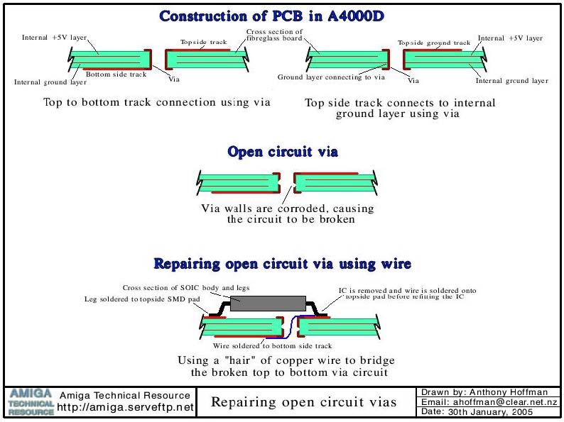
9. If there were signs of corrosion underneath the capacitor when you removed it (green/white powder), you will need to check tracks and vias (the small holes through the PCB) to see if any are open circuit and repair them as necessary. Do this now and make sure track and via repairs don't stick up too high, or you'll have trouble soldering on the new capacitor. Most repairs can be done using thin stands/hairs from a piece of fine electronic hookup wire. The corrosive electrolyte spreads around the capacitor. It commonly runs down inside via holes and corrodes them, so check and repair these as required. This diagram shows a cross section of the PCB and how it's made, as well as illustrating how to solder a wire to top and bottom side tracks in order to repair an open circuit via.
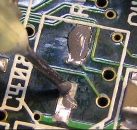
10. Next we're ready to fit the new capacitor. Apply a little SMD flux to the legs of the capacitor, and to the pads on the board. This makes the solder flow and attach itself to the metal much easier. Get the solder paste syringe and squirt a bit out onto a piece of scrap paper to make sure you've got a nice clean flow. Squirt a small blob onto both solder pads as shown below. You mainly need the paste near the outside of the pads, it's not so important near the inside. You don't need as much solder paste as you might think, the amount shown here is probably a little excessive, but it's not overly important.
Tip: store your solder paste in the refrigerator when you're not using it. This slows it from drying out and it's still perfectly usable many months, even years past it's expiriy date!
11. Place the capacitor into the circuit board, double checking you've got it round the correct way. The two diagonal corners on the black plastic base should match up with the footprint symbol, printed onto the PCB in white silkscreen. This side is usually maked with a + symbol on the PCB. The negative side of the capacitor is indicated with a large black stripe on the top side, this side goes away from the + markings on the PCB. Line it up by looking down on top of it, using tweesers or a spike to gently move the capacitor around until it lines up perfecty in the centre of the pads.
12. Using the tip of a small screwdriver in your left hand (if you're right handed), press down gently but firmly on the top of the capacitor to hold it in place. In your right hand, use a hand soldering iron to heat each of the legs which will melt the solder paste. You may need to heat the leg for a few seconds each to sufficiently melt the solder paste underneath. If it doesn't seem to be soldering that well, add an extra dot of fresh solder paste to top of the capcitor's legs. Do not touch the needle of the solder paste syringe with the soldering iron as you'll cause it to melt inside the needle, which will become blocked.
You can see this new capacitor has a 25V rating as opposed to the old one which was 16V. I've used this because I didn't have any 16V ones left. It's OK to use capacitors with a higher voltage rating than the original, but not lower! You may also notice the 25V capacitor is slightly larger than the original, but fortunately it still just fits!
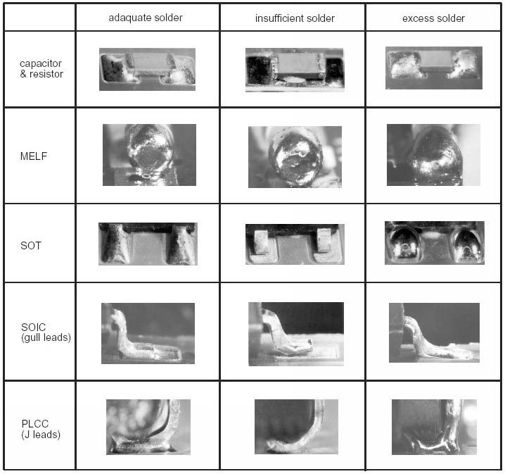
13.Check carefully for badly soldered joints. By gently rocking the capacitor sideways, you'll feel if it's reliably soldered or not. Here are some examples of good and bad solder joints.
Lastly, you may want to use isopropyl alcohol or flux cleaner to clean away the resin and soldering residue left over from the solder paste. The job is now complete!
Home | Audio | DIY | Guitar | iPods | Music | Links | Site Map | Contact
![]()