|
|
Home | Audio | DIY | Guitar | iPods | Music | Brain/Problem Solving | Links| Site Map
This work is licensed under a Creative Commons License.
Building an Effects Pedal
What follows are some tips pulled from the BYOC Forum. BYOC is a great place to get started with building your own effects pedals, and the forum provides a lot of support.
The following are some tips I've put together to help the beginner to have a working FX pedal when they are done. They are by no means "written in stone" rules that you must follow. Just suggestions to help you get thru your build with a minimum of errors. The parts and materials shown in the photos are not representative of the materials used in the kits. They are what I have used personally to build my own pedals so please don't write to Keith complaining that your kit didn't arrive with the same parts and materials shown in my photos.
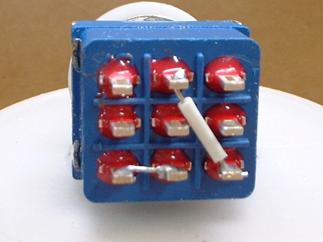
Let's start with the wiring of the stomp switch. In many cases I've seen builders use bare wires for the jumpers between solder lugs on the switch. IMO it is NEVER a good idea to leave bare wire exposed. They are a short circuit risk and should not be used anywhere in a build. Too many times I've seen builds that have very sloppy solder joints to the lugs. Often times there are stray strands of wire sticking out in several directions that can short out against other nearby solder lugs. Another problem I see is way too much solder being used. You should not have a blob of solder on the lugs. All you need is just enough to flow around the wire and lug so it looks as if the two were dipped in mercury. Here I've used a short section of insulation from a piece of wire to insulate the jumper going from lug 4 to lug 9. The jumper is just a piece of clipped off component lead. What I like to do is install the jumper and then bend it around the lug a little so that there is a good mechanical connection between the jumper and solder lug. Notice that I have soldered the top of the jumper to the lug #4 but have also left room in the lug for the wire from the input jack. This ensures that when I do install the input wire that there is already a good connection between the lug and jumper so I don't have to flow excess solder into the joint to solder both connections to the lug. There isn't much need to insulate the short jumper between lugs 3 & 6 since they are so close together.
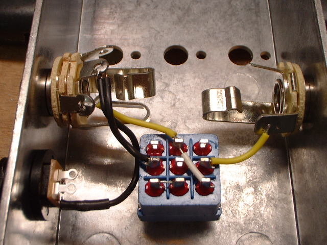
Here's a shot of the switch installed and connected to the jacks. Try to keep your leads short and neat. Good wire dressing is important for a successful build. You don't want to leave a lot of exposed excess bare wire in these areas.
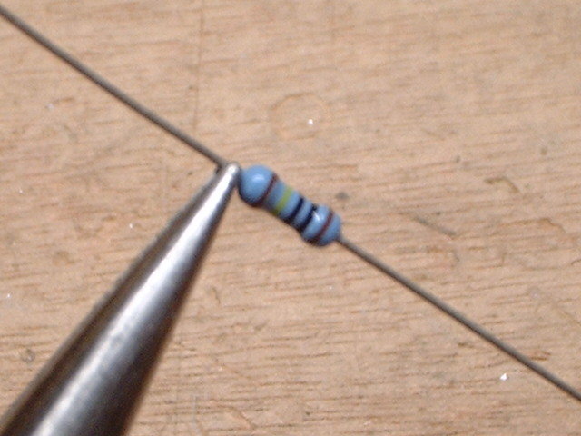
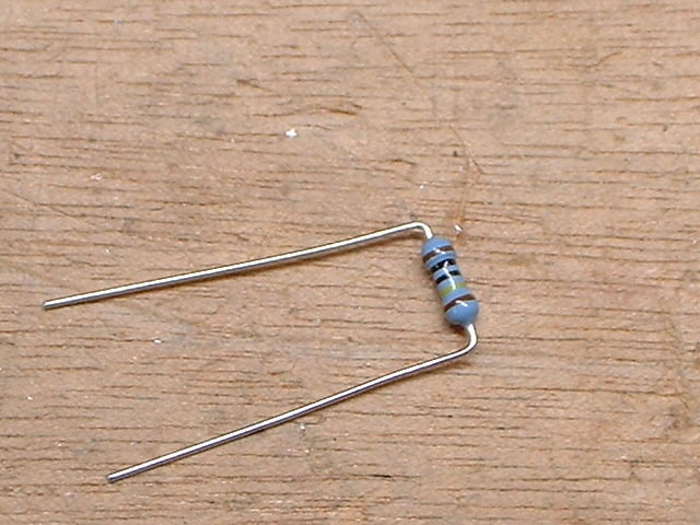
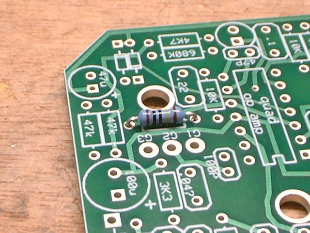
I like to use a small set of needle nose pliers I have to bend component leads before installing them. This way there is no stress placed on the junction between the lead and the component. I've read posts where the builder has broken off a lead to a transistor for example because of the stress they placed on it when bending the lead. Using the pliers as I have described will help prevent this from happening.
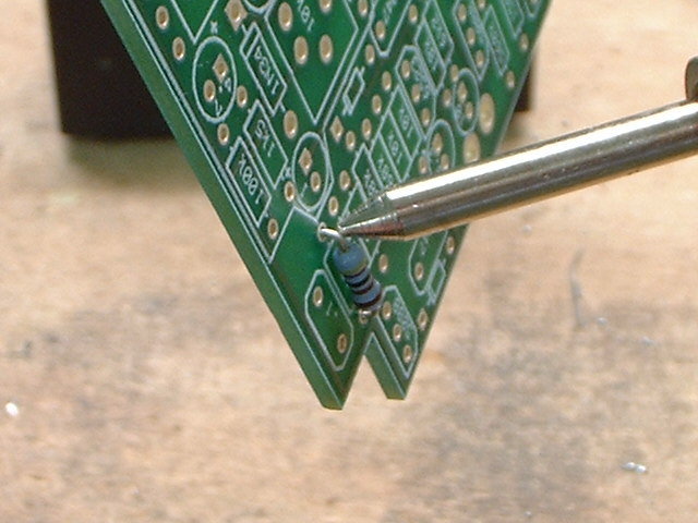
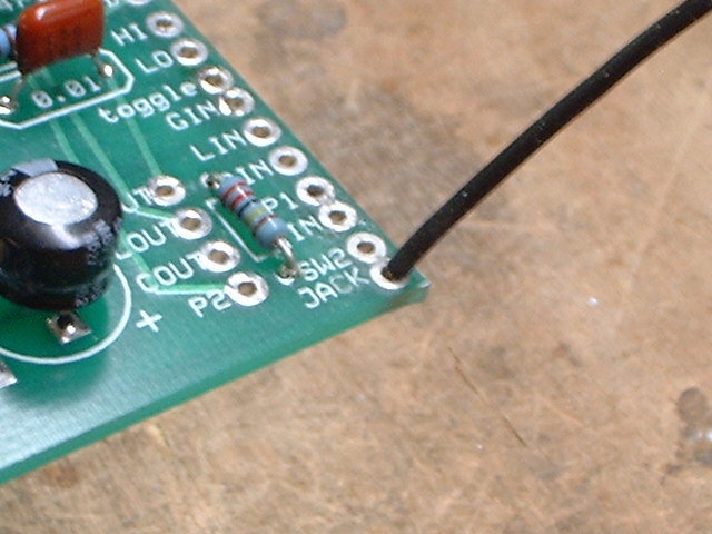
Here the resistor has been installed. Notice that the resistor is lying flat on the circuit board. These are not power resistors that need to dissipate heat so there is no need to suspend them above the circuit board like I've seen many builders do.
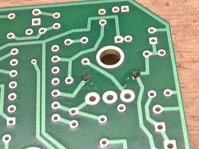
This is the under side of the resistor. You'll notice that the excess component lead has been cut off all the way down to the solder joint. Too many times I see new builders leaving these leads sticking out of the solder joint about 1/4" or so. Do NOT do this. This is another sure way to cause a short circuit.
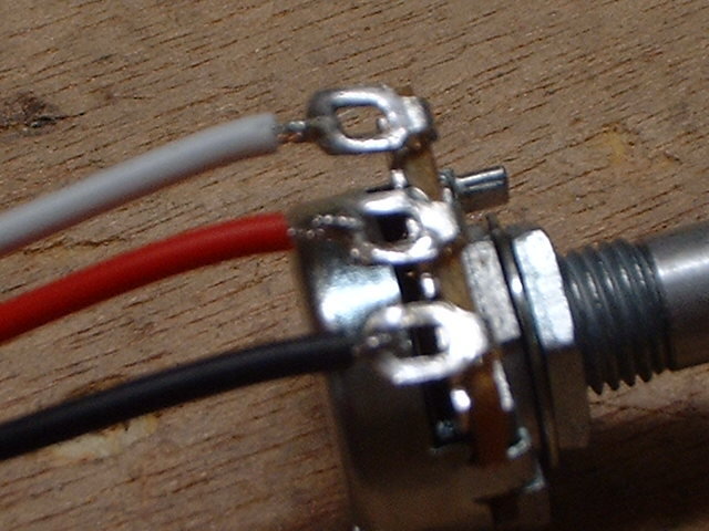
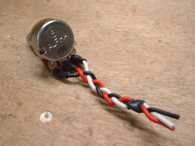
Here is a shot of the wires soldered to the lugs of a pot. I like to use color coded wires on my builds. This will help to prevent wiring errors when you go to attach the other end of the wires to the circuit. The kits do not come with color coded wires so please do not write to Keith to complain about it when you get your kit. This is merely a personal decision on my part from my many years of building electronic devices.
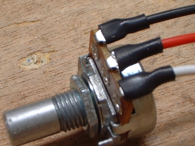
I also like to insulate the lugs afterwards with heat shrink tubing so that there is no way for the lugs to short out against anything. Again, this is a personal decision on my part.
To make things nice and neat I like to braid the wires together before installing the pot.
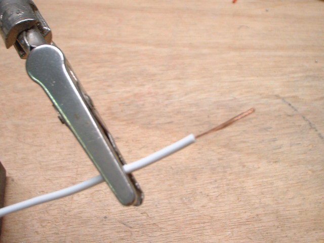
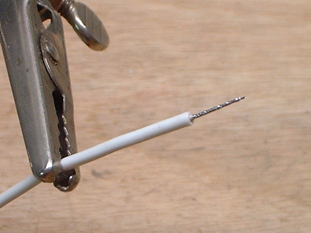
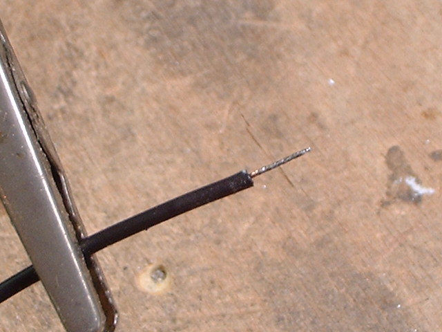
I cannot count the number of times I've seen builders just stick the ends of wires into solder lugs with stray strands of wire sticking out all over the place. This is a very bad habit to get into. Always tin the wire ends first. Here is a piece of wire that has had too much insulation stripped away like I see in a lot of builds.
More often than not I see this stuck into a solder lug and soldered with strands of the wire going 10 different directions. Most of the time the solder joint is cold. This means the parts were not heated up enough to get good flow of the solder.
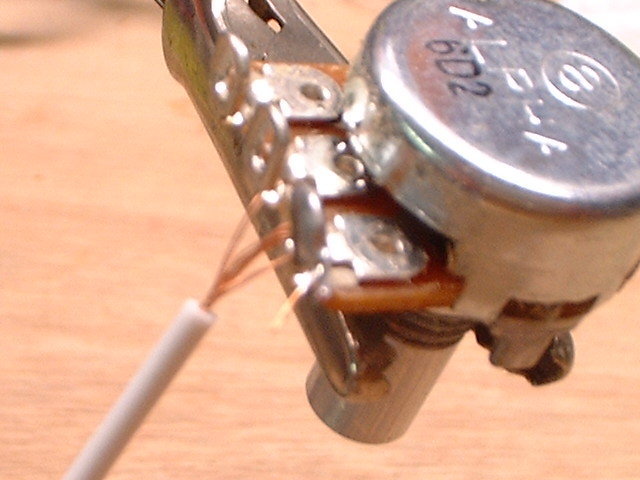
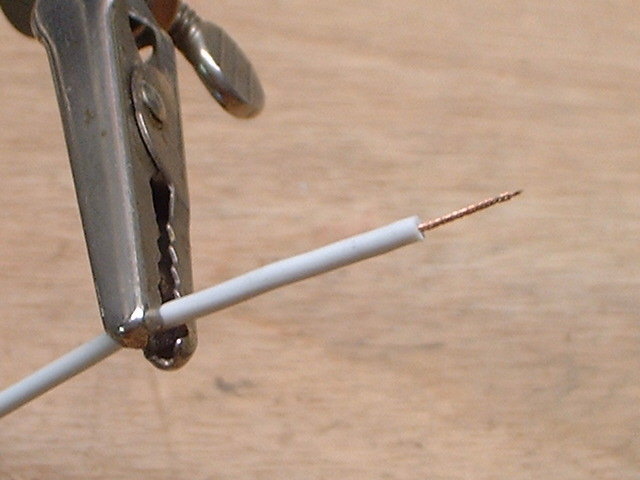
Here is a section of wire that has only had about 1/4" of insulation removed. Once the insulation has been cut remove it using a twisting action. This will twist all the strands together and they will ALL go into the lug when you insert it into the lug.
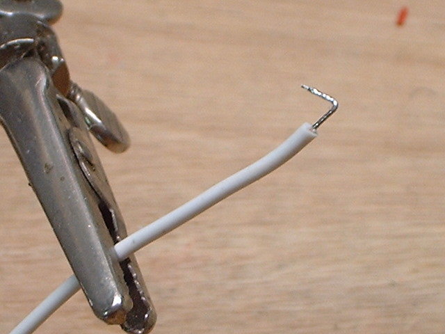
Now heat the wire with your iron for just a second. Then touch the solder to the exposed wire. This is tinning.
Bend the tinned wire end like this.
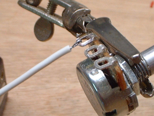
Insert the tinned end of the wire into the solder lug and lightly crimp it down. This is a good example of the mechanical connection I spoke of earlier.
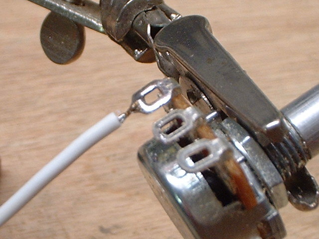
Now that you have a good mechanical connection solder the wire into place. Heat the solder lug and then apply solder to the junction of the lug and the wire. This should only take a second or two. Notice how smoothly the solder has flowed onto the lug and around the wire. If you have a blob of solder you didn't adequately heat the lug before applying the solder. You'll notice that the solder lug is not completely filled with solder. There is no need for this.
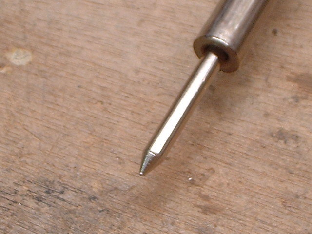
Here's how to solder a component to the board. Start with a conical tipped soldering iron. I use a 25W Weller pencil iron myself.
Plug it in and let it set for at least 10 minutes so it can get good and hot. If you don't have a soldering station you should at least have a damp paper towel close by to wipe the tip of your iron on. Keeping the tip clean is very important for good heat transfer. With the iron heated up and the tip clean melt a tiny bit of solder onto the iron's tip. This is tinning the iron. It helps promote good heat transfer to whatever you are soldering.
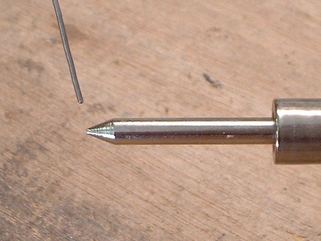
Take a resistor and bend it so it will fit into it's spot on the circuit board. With the resistor flat against the board spread it's leads out so that it cannot fall out of the board when you flip it over. Spreading the leads also helps to get them out of the way when you solder them. Touch the tip of the tinned iron to the junction of the lead and solder pad. It should only take a second to heat up. Now touch the end of the solder to the junction between the lead and the solder pad. It only takes a little. You don't have to flow solder all the way thru to the other side of the PCB for a good solder joint. Not having a blob of solder on the component side of the circuit board will also make it much easier to remove that component if you accidentally put it in the wrong place on the circuit board.
When you're done you should have solder joints that look like tiny Hershey's Kisses (below.)
EDIT: After re-thinking this, the "Hershey Kiss" description of a good solder joint can be a little misleading. It still applies when soldering on a single sided PCB that doesn't have plated thru holes. However, when you have plated thru holes like those on BYOC circuit boards it's a bit of a different story. Since the holes are plated there is bound to be some solder that bleeds thru to the component side of the PCB. When this happens the solder joint on the solder side of the PCB may not always turn out with that "Kiss" shape to it. In fact a lot of times the "Kiss" shape ends up on the component side of the board. As long as the solder that bleeds over to the component side doesn't look like a ball your solder joint should be good. If you've got a ball or blob of solder on the component side of the board you're using too much solder.
Desolder
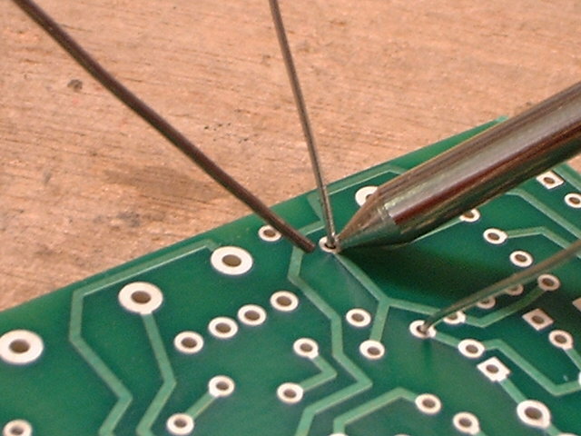
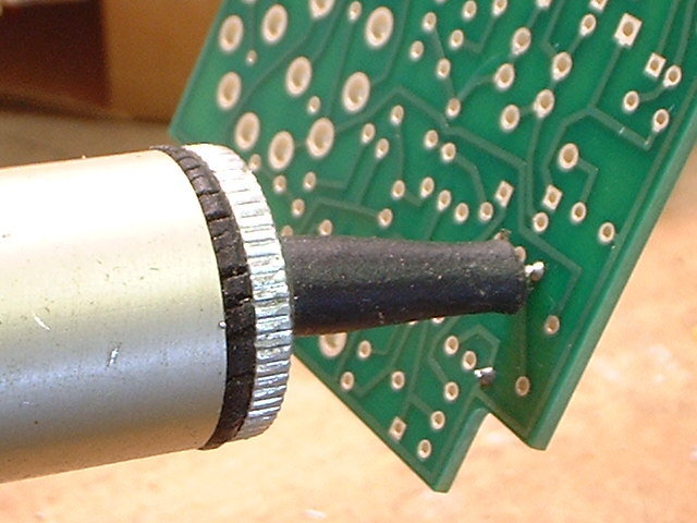
Here are a few tips on how to de-solder a component. I usually use my de-soldering iron to remove components. This method usually works like a charm but the dual sided BYOC PCBs with plated thru holes can present a problem. Especially when too much solder is used and there is as much solder on the component side of the board as there is on the solder side. In difficult cases like that I'll use an iron and a solder pump. You'll need either a set of helping hands to do this or have a friend close by that can lend a hand to hold the PCB steady as you remove the solder. Start by heating up the lead on the component side of the board. Try to do this as quickly as you can to keep excess heat transfer to the component and PCB to a minimum.
At the same time press the pump against the board so it forms a seal around the solder joint. This makes sure that the solder pump pulls the solder out of the hole instead of allowing air to leak around the tip of the pump.
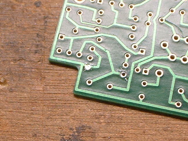
Now let's say that you successfully removed the component but one of the holes is still filled with solder like it is here.
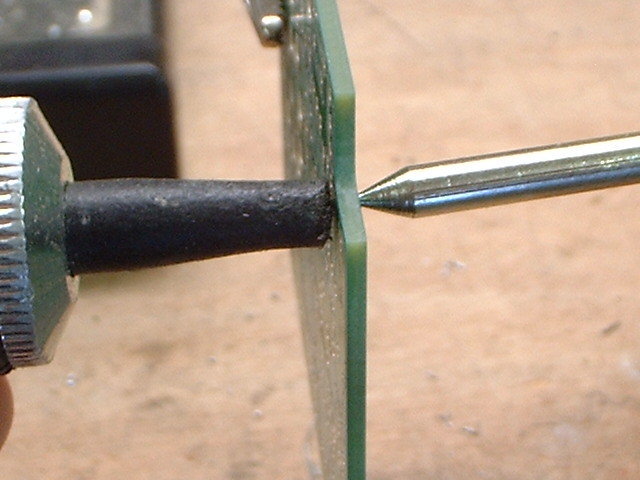
To remove the solder hold the iron against the hole and the pump over the hole on the other side. Heat up the solder and hit the button on the pump to suck out the excess solder. Again, you want to try to do this procedure quickly to keep excess heat transfer to the solder pad to a minimum.
Presto! You're done. Another way to clear the hole of solder is to heat it up and then quickly tap the board against your bench top. A third option would be to use a small hand drill (NOT a power drill) and drill bit to remove the solder.
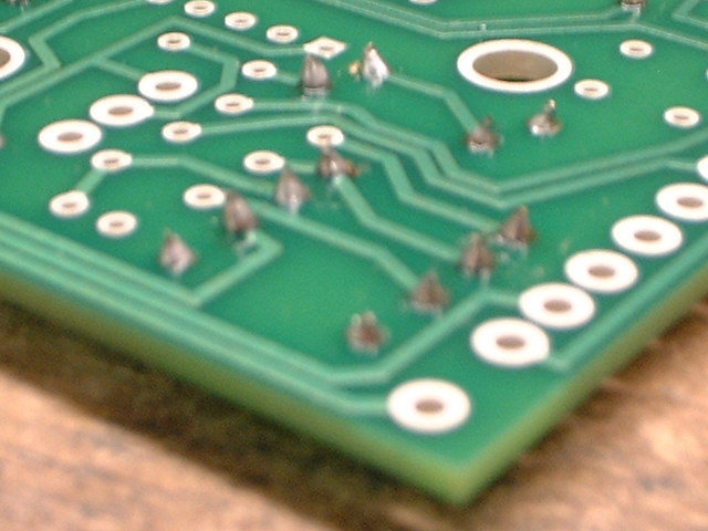
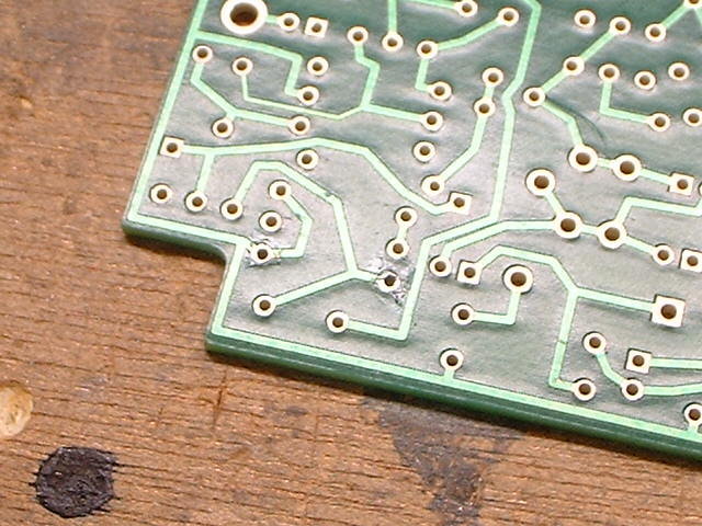
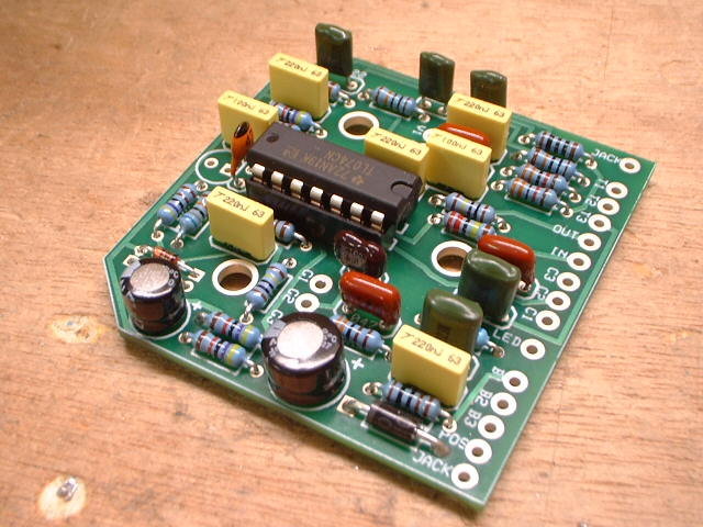
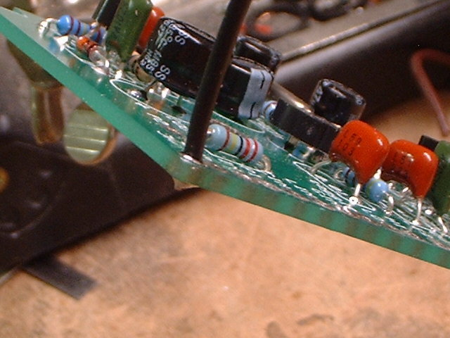
Here is what a cleanly assembled circuit board should look like. Notice that there are no components suspended in the air above the board and that there are no globules of solder coming thru any of the lead holes. Except for a little on the 1N4001 diode. It has thicker leads than a resistor and the thru holes are larger so a little excess solder flow here is hard to avoid.
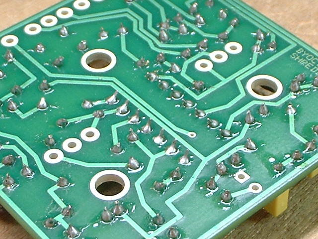
This is what the under side should look like. Notice how the solder joints look like tiny little Hershey kisses. If your solder joints don't look like this you need to take some time to practice. The better you are at soldering the more likely you are to have a successful build when you are done.
Installing IC's
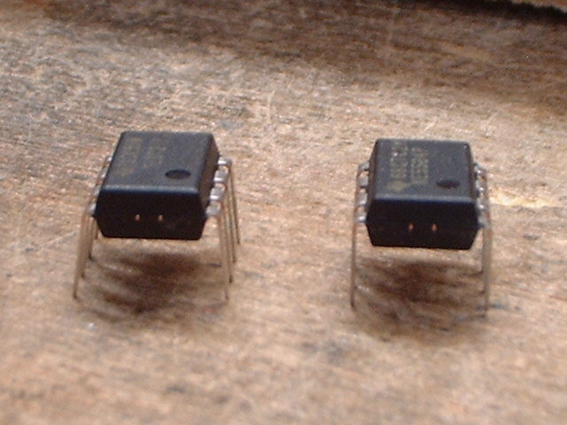
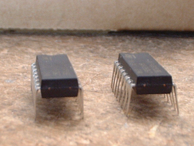
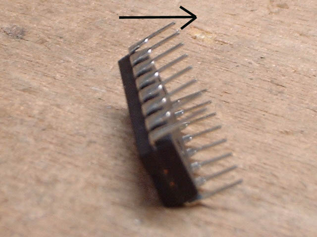
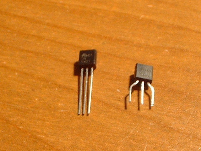
Here are some tips on how to install an IC (Integrated Circuit) chip. You'll notice that when you look at the chips that the legs are spread out like the chip on the left in this photo and the one on the right in the photo below. These spread out legs make it hard to insert the chips into the sockets because the pins need to be perpendicular and not angled. Having the legs going straight up and down makes them much easier to get into the IC sockets.
What I do is place the chip on it's side and gently press down and roll it against the table top to evenly bend all the pins straight. Be VERY careful when doing this or you could end up bending all the legs over flat. Once you've done one side do the same to the other. You want your chip to look like the ones above with straight up and down legs.
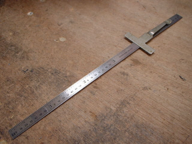
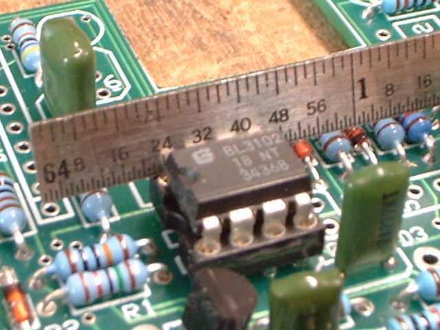
Now comes the tricky part of getting the chips in the sockets. The larger the chip the trickier this can be. What I do is use a straight edge to help me install the chips like this 6" scale I use.
Start by inserting the legs on one side of the chip into the socket. Then rest the straight edge up against the other row of legs and use it to keep all the legs in line so that they slip down into their respective slots in the socket as you push the chip in. This technique comes in really handy especially with larger chips.
Installing Transistors
Here's a tip for installing transistors into sockets. I'm always seeing new builders sticking the trannies in the sockets with their full lead lengths. To make matters worse they are leaving these leads exposed where they can easily short circuit. Once you have the build up and working trim off the excess lead from the tranny and bend the leads so that the tranny is lying down and won't get in the way when you put the cover on the enclosure. You might also want to consider color coding the leads as I have done in the photo with insulation stripped off of sections of wire.
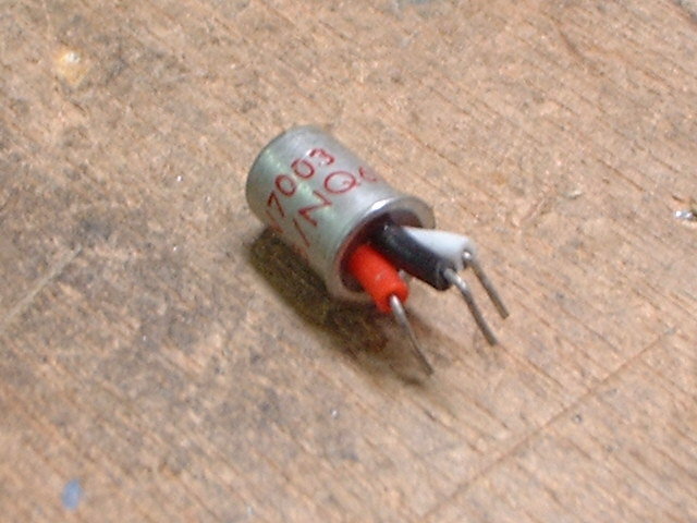
Here's a tip on how to install transistors into the small snap-off sockets. I use a small set of needle nose pliers to bend the leads so that their spacing better matches the spacing of the sockets. (Some transistors come from the manufacturer already spaced out. In those cases all you have to do is cut off the excess lead.) Once I've done that I cut off about 1/4" from the ends of the transistor's leads. Now insert the leads into their respective sockets and gently rock the tranny back and forth till you feel the leads sliding into the sockets. They should go in about 1/8" or so.
Tip: Always measure the value of the resistor you are about to install. Often times I see newbies that don't know how to read the resistor's color code ending up with the wrong value resistor in the circuit. Then more often than not they try to place the blame on a bad component when their build doesn't work. This just amazes me. The chances of you getting a bad component are extremely low. I mean think about it for a second. You know little or nothing about electronics and the first time you try to assemble a circuit and it doesn't work do you honestly think it's going to be because of a bad component and not your lack of knowledge about electronics?
Soldering Wires to PCB
Take your time, learn how to solder correctly and follow these guidelines and the build instructions and I can almost guarantee that you will have a working pedal when you are done. If you run into any snags along the way assume nothing and ask questions here on the forum.
Here are some tips on how to solder a wire to the PCB. The biggest mistake that I see is the builder will strip off about half an inch or more of the wire's insulation and leave a bunch of bare wire exposed after soldering the wire into the PCB. Do NOT do this. Leaving exposed wire like that is a short circuit risk.
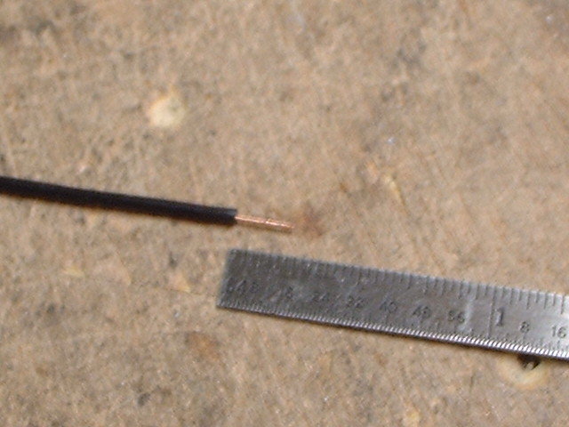
Start by stripping off about 1/4" of insulation.
Now tin the exposed wires. A lot of noobs will just strip off the insulation and shove the exposed wires into the PCB. A lot of times this will lead to stray strands of wire not getting inserted into it's eyelet and possibly shorting against an adjacent eyelet or component. By tinning the exposed wires you assure that all of the strands get inserted into the correct eyelet.
Now insert the tinned wire all the way into the eyelet so that the insulation butts up against the PCB.
Solder the wire into place and clip off any excess wire sticking thru the PCB all the way down to the solder joint. Do NOT leave excess wire sticking thru the PCB. This is another short circuit risk.
Working with Pots
Home | Audio | DIY | Guitar | iPods | Music | Links | Site Map | Contact
![]()