Home | Audio | DIY | Guitar | iPods | Music | Brain/Problem Solving | Links| Site Map
This work is licensed under a Creative Commons License.
How to Pick Audio Capacitors
So, you’ve decided to repair/upgrade your vintage audio equipment by replacing the capacitors. When you go to Mouser or Digikey, however, you are presented with tens of thousands of choices. Even after drilling down to the specified capacitance and voltage, you have dozens of candidates, differentiated by such esoteric terms as Tan Delta, Q Value, ESR, etc, etc, etc. Here’s what you need to know to pick the best capacitor for the job, without spending a fortune on Super Fancy Audio Capacitors.
First, a quick review of what capacitors are and how they work: You can think of a capacitor as a bucket o’ electrons. All capacitors have two layers of conducting material, with a layer of non-conducting material between. The non-conducting material is referred to as the dialectric. What makes a material conduct is that it has a large number of possible electron configurations, so that at any time in a metal there are a cloud of loose electrons wandering from atom to atom. When you apply a positive voltage to one side of the non-conducting plate, it pulls electrons off of that plate, much like lower air pressure in a room that you’ve just taken the air pressure out of (electrons are negatively charged, and so they are attracted to a positive voltage). The lack of electrons on the positive plate induces a greater number of electrons on the negative plate, giving it a net negative charge.
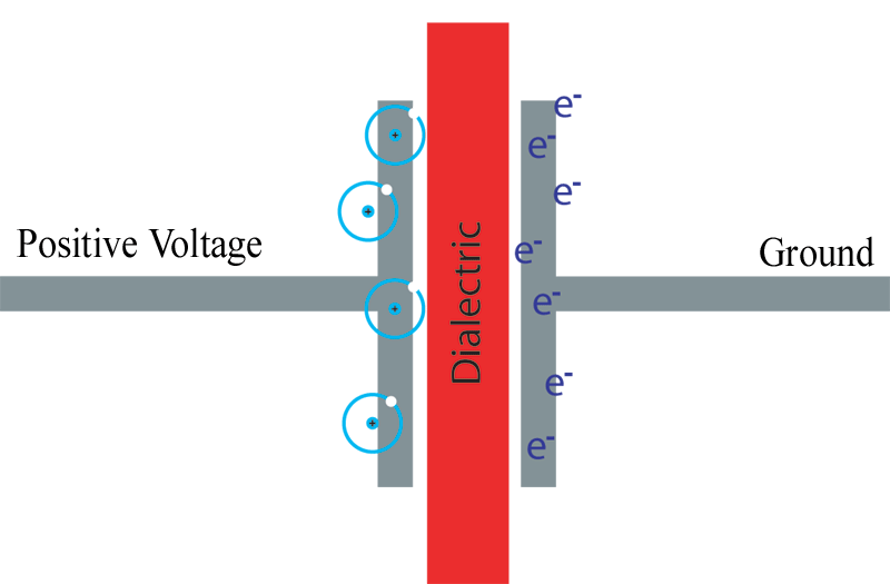
A capacitor diagrammed. On the right, a concentration of electrons. On the left, a concentration of atoms missing electrons (holes).
The astute reader will notice that as the electrons are actually travelling towards the positive voltage. The direction of current travel shown in most electrical schematics is actually the opposite of the direction of charge carrying particles. We have Ben Franklin to thank for this incorrect convention, and in some European schematics, particularly older ones, the current orientation is shown correctly.
This is probably the point where I should talk about electrical safety when working with large capacitors. Capacitors store electrons, and if you place yourself between those electrons and a ground, they will shock you, and it will hurt. What makes this particularly easy to do is the fact that the entire metal chassis of the amp is the ground, much the way your car is wired. So here’s what you should do after you unplug the amplifier and before you start rooting around in there:
Check the positive terminals of all your large filter capacitors with a multimeter, on DC voltage. If it reads less than 12V, it won’t shock you, but you still might fry another component by shorting it to the capacitor with your metal tools.
If you have a cap that still has some juice in it, connect a 1Kohm (1000ohm), 5W resistor across the leads and let it discharge until the voltage reads zero.
Capacitor Quantities: There are four main specifications for capacitors.
- Voltage: This is the maximum voltage that a capacitor may be subjected to without dialectric breakdown. Dialectric breakdown occurs when the electrical field between the two plates of the capacitor become strong enough for the dialectric to polarize and become a conductor. When this happens, the capacitor will become hot. Then it will smoke. Then it will catch fire or in some cases explode. So when you are ordering the capacitors, you should pick ones with an equal or higher rated voltage. There’s no advantage in going with a larger voltage, and doing so will mean a larger capacitor, which can be harder to fit in the amp.
- Capacitance: The unit of capacitance is the Farad, one Coloumb-Volt. A coloumb is a truly ridiculous number of electrons, so typically capacitors are measured in microfarads- mF or uF or (Greek letter mu)F. A microfarad is 1/1,000,000 or 1×10^-6 of a Farad. Picofarads are also used, which are 1/1,000,000 or 1×10^-6 of a microfarad (1×10^-12 of a Farad). So you can divide or multiply by a million to move between these quantities.
- Tolerance: This is the acceptable variation on the value. So a 47mf capacitor with -20%/+80% tolerance would have a capacitance of anywhere from 37.6mf to 84.6mf (although the values for new electronics are typically quite close to the specified value).
Dialectric: The fourth way that capacitors are specified is by dialectric, the type of material separating the metal plates. There are three common types of dialectric.
Ceramic: the dialectric is porcelain, giving these capacitors long life and high voltage, although with low capacitance. Often, they are a tan/brown color, and usually disk-shaped although sometimes tubular shapes are used (the tubular ceramic capacitors may be replace with ceramic disk capacitors). Generally, these capacitors do not degrade over time, although they can be checked for mechanical/heat damage, and also continuity. Because they can store charge, the continuity tester may briefly beep or light up, but should not stay on
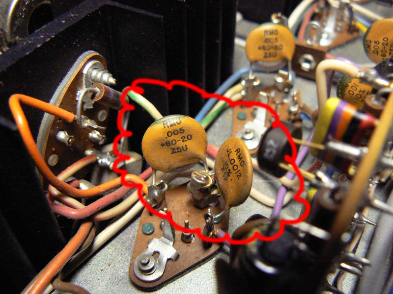
Ceramic disk capacitors
In the picture, two capacitors are shown. The one on the left reads:
RMC = manafacturer
.005 = .005mF
+80-20 = +80%, -20% tolerance
Z5U = the subtype of ceramic dialectric (you don’t have to match this if it’s a pain).
What’s missing here is the voltage rating, so you’ll have to go to your service manual for that. If you can’t find it, you’re usually safe with 250V or higher.The one on the right reads:
RMC = manafacturer
JL.0012 = .0012mf (the JL means something but I don’t know what)
10% = +/- 10% tolerance
X5F = Dialectric subtypeThere’s a good reference to ceramic capacitor markings here.
Film Dialectric: in film dialectric capacitors, the dialectric is some kind of plastic, such as mylar or polypropylene. This dialectric allows a high voltage and long life, but at a downside of being relatively large and expensive. There are a bewildering array of possible dialectrics in this catagory, but on the recommendations of people who know more about this stuff than I do, metallized polypropylene is a good and inexpensive choice for audio applications.
Film capacitors generally do not wear out, so replacing them is more in the upgrade catagory then restoration. However, because electronics in this area have improved tremendously in the past however may years since your amp was built, it can still be worth doing.
Be advised that as film capacitors are often used in the signal path, and the newer film capacitors have improved electrical characteristics, you may change the sound of your amp by replacing them. Maybe for the better, maybe for the worse. There’s a lot of art here in the intersection between the objective electrical characteristics of the capacitor and the subjective assessment of how good it sounds. The good news is that electronics parts are cheap, so if you don’t like what you get you can try something else.
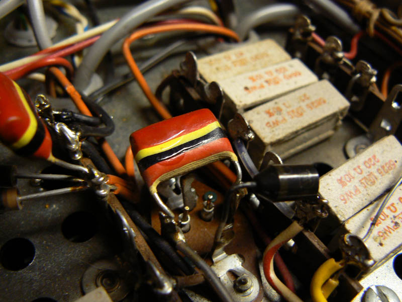
A film capacitor with the color band style of marking, now rarely used.
The picture above shows a film capacitor with the color band style of marking. These can be a little tricky, and the web has a number of different and sometimes contradictory answers on how to read them. But in general, they work like resistor color codes.
In the diagram, the color bands are:
Red: first digit = 2
Red: second digit = 2
(there’s no line between the two red bands, you are supposed to recognize that this is actually two bands).
Yellow: multiplier = 5, i.e. multiply by 1×10^5mF
Black: maybe tolerance?
Red: first digit = 2
Yellow: second digit = 5, so 250V?So I get .22mF 250V.
I guess, anyway. I actually went to the schematic and read the specs off that.
Electrolytic Dialectric: In this type of capacitor, a chemical insulator is applied to one of the foil plates. This allows for a much thinner dialectric than other types of capacitors. Capacitance, you’ll remember from E&M, is directly proportional to the area of the plates and inversely proportional to the distance between them, so this design allows extremely high capacitance in a very small volume at low cost. This makes electrolytic capacitors ideal for power filtering, as the larger the cap, the less ripple current. Electrolytic capacitors come in a variety of forms, the attached images show a few of the more common varieties.
Radial(top) and axial (bottom) electrolytic capacitors. The form factor does not have any effect on electrical/audio performance.
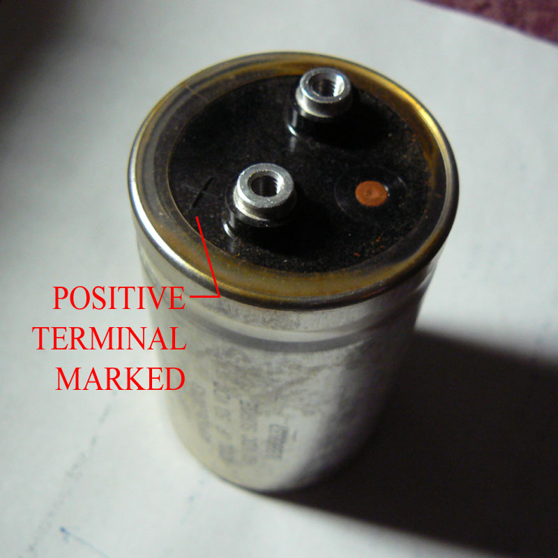
A large can-type electrolytic capacitor.
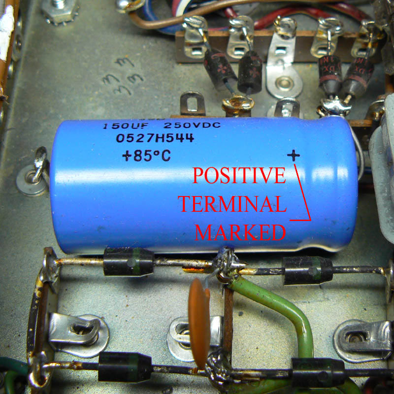
A large axial electrolytic capacitor.
There are a number of downsides with electrolytic caps
- They wear out. As time works it’s ravages, the electrolytic breaks down, causing the capacitor to lose its ability to store electrons and become more of a resistor than a capacitor. If you buy an amp at a garage sale, it’s always a good idea to at least replace the filter caps before you turn it on for the first time, because otherwise you can fry your transformer. You’ll read about how you can ‘reform’ electrolytic capacitors by applying a small voltage to the capacitor for 15 minutes to rebuild the polarity of the dialectric. My take: don’t screw around with it, just replace them. Electronics parts are cheap, your amp is not.
- They are (generally) polarized. One lead of the capacitor must always be at a lower voltage than the other, otherwise the electrolytic will break down. An electrolytic capacitor connected in reverse will get hot and emit a very distinct smell, something like fish frying in a vat full of chemicals. This is the electolytic vaporizing. The polarity is marked in a variety of ways, look at the above images. The one exception to this rule is bipolar or non-polar electrolytics, which will be clearly marked with a “BP” or “NP” on the schematic. These are very much the exception; in the Mac 1700 there are only two, in the power protection circuit.
- They are leaky. Even a new electrolytic cap allows a considerable amount of current across the plates; this makes them less than ideal for audio signal path usage. You can replace the electrolytics in your amplification stages with film capacitors; as I said above, doing so might improve your sound, or not. Parts are cheap, try it and see what you get.
Other capacitor characteristics: Because of the wide number of applications of electrolytic capacitors, there are a wide variety of characteristics that you’ll have to choose between when you’re matching the parts. Here’s my take on them:
- Low Impedance: Impedance is composed of two parts, resistance and reactance. Resistance is probably familiar to most of us, it is the opposition to direct current (i.e. current that does not vary with respect to time) in a circuit, governed by the relation:
Voltage = Current * Resistance
Reactance is the analogous property for time varying currents, such as audio currents. Now, ideally capacitors do not transmit direct current at all, as there is no direct connection between the plates. So impedance as it applies to capacitors is mostly a function of reactance. I say mostly, because real-world capacitors do leak some DC, but not enough that we can’t use the ideal model. The formula for reactance in ideal capacitors is:
Reactance = 1 / (2 * pi * frequency in Hz * Capacitance)
So a capacitor will have a greater reactance to low frequencies, and the larger the capacitor the lower the reactance. What impedance really represents for an audio application is how much distortion a capacitor injects into a frequency passing through it, by pushing back against a time-varying current. This makes low impedance one of the more important characteristics of a capacitor in the signal path, less so for a filter capacitor.
- 85 C / 105 C: The maximum operating temperature of the capacitor. Now, keep in mind that 85C is 185 degrees fahrenheit, more than enough to cause burns. My take on this is, if your capacitors are running this hot, there’s something else wrong in your system, or you’ve got the capacitor in backwards. So 85C is fine for audio applications.
- Low ESR: ESR stands for Equivalent Series Resistance. This can mean different things depending on the type of component, but in a capacitor, it is the voltage loss due to resistance in the metal leads and plates. A typical ESR for a capacitor might be .1Ohm, whereas a low ESR model might be .01ohm.
Low ESR seems to be a much touted feature for audio capacitors, especially Black Gates. Since resistance is not dependent on frequency, however, I don’t understand how ESR would have any effect on distortion in the audio signal, and I doubt you’re going to hear a difference between .1 and .01 ohm. If you want to make a case for it, the comments are your oyster.
- Low Leakage: An ideal capacitor doesn’t have any electrical connection between the plates, so there would be zero DC current across the capacitor. This is not an ideal world, and so real capacitors do leak DC. The formula given in the spec sheets is of the form:
Leakage current = Constant * Capacitance * Voltage,
The constant is typically on the order of .01 or less, and varies with the line of capacitor.
For audio purposes, we don’t care how much leakage occurs when the amp is turned off. It can be significant for filter capacitors, however. Leakage current is proportional to the capacitance and voltage, and filter capacitors have a lot of both. In addition, they are being charged at the relatively low frequency of 120Hz, and so how well they keep that charge between the variations in the power affects the amount of ripple current you hear on the other end of the capacitor.
- High Ripple current: this specification can be a little confusing, since I already defined ripple current as the variation in filtered DC voltage on the load side of your filter capacitors, and the lower the better.
Here, however, it means that the capacitor can withstand high time varying currents without heating itself up so much that it fails (via Ohmic heating due to reactance). This is one of those specs, like rated voltage, where as long as you meet it it won’t affect you one way or the other. Thing is, you won’t find the rated ripple current for any of your original capacitors. I’m going to hazard a guess that, as electronic components have improved considerably since your amp was built, the rated ripple current of almost any new capacitor that you put in there will be higher than spec. But if it’s a tiebreaker, go with the higher ripple current.
- Long Life: There are two aspects to long life, a long shelf life or a long rated life.
Long Shelf Life: As mentioned previously, the dialectric of an electrolytic capacitor will break down if the positive lead is not kept at a higher voltage than the negative lead. Capacitors aren’t generally going to sit around long enough before you put them in your amp for this spec to matter. But if your amp goes through long periods of disuse, perhaps because you can’t stop buying them at garage sales, then this is the capacitor for you.
Long Rated life: This is the number of hours that a capacitor will function under load without dropping below, say, 80% of it’s rated capacitance. If you go with a long rated life, you might have to replace your electrolytics every 30 years instead of every 20.
- Radial/Axial: This refers to where the leads are on the capacitor. In an axial capacitor, the positive and negative leads are at opposite ends of the cap, whereas in a radial capacitor they are on the same side. Both varieties are shown in post #19, in the first picture. There’s no difference in electrical/sonic characteristics, so it’s just a matter of how the capacitor is physically going to fit in the space provided for it.
On my 1700, the original capacitors were all axial. I used all radial capacitors (I was unable to find ones with the characteristics I wanted in axial form), and it worked out fine for me. I bent the leads as shown in the picture so that I wouldn’t have capacitors sticking out all over the place, but that was a cosmetic decision, there’s plenty of room in the chassis to have them sticking up.
A radial capacitor may be used to replace an axial capacitor by bending the leads like so.
- Tan delta/Loss dissipation factor/Q factor: This is a number representing the total efficiency of the capacitor. You know how a capacitor gets warm when in use? That heat energy doesn’t come for free, it is the energy lost in charging and discharging the capacitor due to resistance and reactance. I’m ending with this specification because it attempts a holistic measurement of a lot of factors, such as impedance, leakage, and ESR. Tan(delta), dissipation factor, and Q factor are exactly the same thing, expressed in slightly different ways:
tan(delta) = charge lost to heat / charge returned
So a tan(delta) of .1 would mean that 1/10th of the energy is lost to heat. Lower is better.
Dissipation factor = tan(delta) * 100%
So the dissipation factor is the percent of energy dissipated. Lower is better.
Q factor (or Quality factor) = 1 / Dissipation factor
So the quality factor is the percentage returned as usable electrical energy. Higher is better.
Q factor + Dissipation factor = 100%
So if you have two capacitors with different Q factors, the one with the higher Q factor is probably your better bet. Alternatively, you could connect them to equivalent AC loads, and see which one stays cooler. But because the dissipation factor can arise from a variety of sources, different capacitors with the same Q factor could be better suited for different applications.
The Upshot: Here’s what to look for, if you were kinda skimming for the last 2,000 words or so.
Signal capacitors: low impedance, long life.
Filter capacitors: low leakage, long life.
Quick and dirty test for people who don’t want to wade through the specs: Low tan(delta), low dissipation factor, or high Q factor.
Where possible, I replaced the electrolytics in my MAC1700 with Panasonic FC or FM series and Nichicon PW or HE series. I also later replaced the film capacitors, which were crumbling into dust due to the amp being stored in a garage in Texas for many years. For those I used Xicon MPP series. My parts list for the MAC1700 may be downloaded here:
For the whole project, including shipping, my cost was about $90. If you want to be a little smarter about where you spend your money (“Computer Grade” capacitors are really fine for the power filtering sections, e.g.), you could probably cut that in half.
Home | Audio | DIY | Guitar | iPods | Music | Links | Site Map | Contact