|
|
Home | Audio | DIY | Guitar | iPods | Music | Brain/Problem Solving | Links| Site Map
This work is licensed under a Creative Commons License.
Impedance 101
Pumping Up the Volume on Vectors
Research for this two-part series reinforced the value of experience. My math skills might have been better in college, but impedance is one of those multidimensional “concepts” that I organically understand and better appreciate now vs. then. Using carefully chosen analogies along with three interface examples, I hope to demonstrate the common, everyday effects of impedance.
The term “interface” is equally important, because it implies the interconnection of two devices—a source and a destination—each having defined impedance. Like the time before the well-tempered clavier—when transposing a song from one key to another was not an option—there are interface combinations that beg for a “professional tuner.”
As you may recall from the last installment, I pointed out that wire is not a perfect conductor—it has resistance—and two wires translate into a complex assortment of series resistance and inductance, combined with parallel capacitance. The long and short of interfacing is simply this: Well-designed equipment can tolerate wiring variations, while other gear live and die by cable performance. Understanding what’s good, bad and potentially ugly will help to maximize performance and minimize destruction to your wallet and your sound.
EXAMPLE 1: HAUT-PARLEUR
A loudspeaker is like a drumhead, tuned real low by a soft edge-suspension material made of rubber, foam or paper. The part you can’t see is a coil of wire centered in a strongly focused magnetic field. Talk about complex impedance, here you have a mechanical resonator mounted to a resonant chamber (a cabinet) coupled with the voice coil, the inductor known as “L” in electrical circles. A loudspeaker is technically a “motor,” but it can also be used to generate electricity just as a dynamic microphone does. As an electromechanical device, it is the perfect example for making impedance tangible.
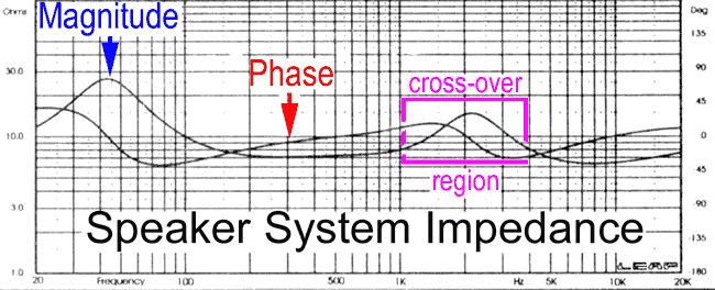
Loudspeakers come in various sizes and shapes for their respective purposes. The published AC impedance will typically be 4, 8 or 16 ohms, often referred to as “nominal,” because the magnitude changes with frequency and is therefore averaged. The DC resistance will be a different number. As you can see in Fig. 1, both impedance (the blue arrow) and phase (the red arrow) meander across the frequency spectrum for a passive, two-way monitor system. Note that the combined woofer and cabinet resonance raises the impedance to a whopping 25 ohms at about 45 Hz!
Figure 1: Sweeping an oscillator through a two-way speaker system generates these very typical impedance and phase variations
TESTS FOR RESONANCE AND DAMPING
To test for woofer resonance, simply insert a 100-ohm resistor in series—between it and the amp—and slowly sweep a sine wave oscillator from lowest frequency to the midband. You won’t need any other test equipment other than ears and eyes to find the resonant “bump.”
The next impedance demonstration also requires a speaker and an amp, but sans resistor. Assuming the power amp is connected and turned on, tap on the woofer and listen closely to the resonance. Now, disconnect one of the amp wires (or turn the amp off) while tapping and notice the difference. (Allow enough time for the amp to be fully “off.”) The transition from a tight, well-damped “tap” on paper to a less-restricted tonal “thud” should be obvious.
The woofer has a natural free-air resonance that changes once installed into a cabinet, either ported (bass reflex) or relatively airtight (air suspension). The speaker’s nominal electromechanical impedance is at least a factor of 10 higher than that of the amplifier’s source impedance. The ratio of the two is called the Damping Factor (DF), which is responsible for keeping the bump in Fig. 1 under control, unless the cable resistance becomes a contributing factor.
Note: While a power amp’s output stage is relatively simple, it can be further reduced to a single component for the purpose of defining its impedance—how the outside world sees it—the result of this reduction process, known as the Thevenin Equivalent, is typically below 1 ohm. Do not confuse this with the recommended “load” or destination impedance found on the back panel of most amplifiers.
MORE SHOCK TREATMENTS
Tapping the woofer with a finger is just the reverse of it reproducing a kick drum; both are impulses that stimulate the woofer and cabinet resonance. Accuracy of reproduction is not always what sounds best to the ear; an under-damped loudspeaker will be the dreaded sonic descriptor, “warmer.” The best way to tame the speaker’s self-expression is by minimizing the cabling between it and the power amp, hence the concept of self-powered monitors (or the use of “monstrously” thick cable).A car outfitted with a spring-only suspension system would bounce all over the road, a spring being a high-impedance device compared to a shock absorber. The amplifier’s extremely low-source impedance appears as a “short circuit” to the woofer’s natural mechanical resonance. You could describe both the shock and the amp as “low impedance devices that provide damping and stabilization to what would otherwise be a bouncy ride.”
Note: The need for damping is the reason a 600-ohm terminating resistor should be connected to the output of transformer-based gear, such as the venerable UREI LA-3 limiter, when interfaced with modern gear. A transformer consists of two coils of wire, the electronic equivalent of excitable springs.
Load Resistor
Frequency @ -3 dB
100 ohm(see note)
800 Hz
1.1 kilohm
160 Hz
2.1 kilohm
80.5 Hz
3.1 kilohm
52.5 Hz
4.1 kilohm
40.0 Hz
5.1 kilohm
31.5 Hz
6.1 kilohm
26.5 Hz
7.1 kilohm
22.5 Hz
8.1 kilohm
19.5 Hz
9.1 kilohm
17.5 Hz
10.1 kilohm
15.5 Hz
Table 1: Various load resistors interact with the series output capacitor to affect the low-frequency roll-off as shown in Figure 3. At -3 dB, the signal level is reduced to half of the power before the roll-off began.
Table 1: Various load resistors interact with the series output capacitor to affect the low-frequency roll-off as shown in Figure 3. At -3 dB, the signal level is reduced to half of the power before the roll-off began.
NON-PLUSSED
That impedance varies with frequency should be more tangible now, what about phase? The magenta square in Fig. 1 shows how a crossover network—consisting of inductors, capacitors and resistors—affects both impedance and phase response, but to make it more tangible…Connect a battery to a woofer and watch how it moves in or out depending on polarity, staying there until the power is removed. Oversimplified, phase is the minute delay of the cone as it attempts to travel to its destination. Once there, the speaker has a strong desire to return from such an exaggerated excursion, acting as a generator when it does. This example should also help to visualize what simple expressions such as “E-L-I the I-C-E Man” did for engineering students. Don’t laugh! Type “ELI the ICE Man” into a search engine, and you’ll be surprised as I was. The best link, http:// ewhdbks.mugu.navy.mil/elecform.htm, yielded a fabulous collection of electronic formulae, rules of thumb and mnemonics.
E-L-I reminds us that Voltage-Leads-Current by 90° (the Phase angle) in an inductor, a coil of wire designated as “L,” “E” stands for voltage and “I” for current. I-C-E reminds us that the reverse is true for capacitors, where Current-Leads-Voltage by 90°, where “C” stands for capacitor. E-L-I the I-C-E is deep, man, but memorable for the purpose of “concept retention.”
GROUND TO LIGHT
Analog audio—in both the mechanical and electronic domains—is slow and easy to understand. The sound of connecting a battery or an amplified kick drum to a loudspeaker emphasizes the keywords impulse, reaction/response time and resonance—all of which can happen at any or all frequencies, from radio and video all the way to light. Impedance is an equal-opportunity vector, equally popular in the data communications realm. Surely, you’ve encountered an SCSI terminator?Walk into Radio Shack for antenna wire, and a knowledgeable salesperson should ask, “300-ohm or 75-ohm?” In this case, the assumed frequency spectrum includes FM radio and broadcast television (88 MHz and beyond). Digital audio’s S/PDIF interface is equivalent in bandwidth and impedance to line-level analog video (6 MHz and 75 ohms, respectively).
To further study the effects of impedance requires math. Plotting a graph of impedance and phase requires several formulae plus multiple calculations at as many frequencies as possible (enough to represent the audible spectrum, for example). Fortunately, I found the perfect application (“Micro-Cap” from www.spectrum-soft.com), which was available as a demo as a free download. I’d still be ciphering if it weren’t for this handy bit of technology, so I’ll spare you the math entirely this time around.
EXAMPLE 2: MAGIC CABLE
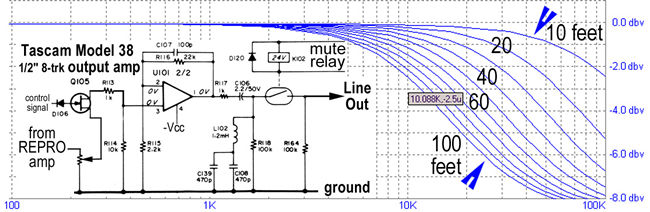
Figure 2: Cable capacitance can load down vulnerable output amplifier designs (click for larger view).
One day, long ago, I walked into a control room to align a Tascam Model 38 analog 8-track. While playing the high-frequency section of the alignment tape, I noticed that the machine’s VU meters did not agree with the voltmeter connected at the patchbay. Eventually, I determined that the cable capacitance was loading down the machine at high frequencies.
Figure 2 shows the effect of cable capacitance on the frequency response of vulnerable equipment. The “inset,” a schematic of the 38’s output circuit, includes a very guilty 1-kilohm resistor (R117) following the op amp. The purpose of this resistor is to protect the output amplifier from accidental short circuits, as well as to provide a “bias trap,” a filter network designed to stop high-frequency bias leakage that could potentially damage tweeters. (Bias is well beyond hearing range, but a little leakage could potentially become a stealth tweeter eater.)
I didn’t carry a capacitance meter on service calls, but this particular customer chose the cheapest possible cable solution, sending me on a minor detour. Back in the lab, several cable tests yielded a typical range of 50 pico-Farads per foot (pF/ft) to a low of 20 pF/ft, this being for foil-shielded audio cable and wire-shielded computer video cable, respectively. These are acceptable values.
FEED THE KITTY
I fed the Tascam 38 output circuit values into Micro-Cap, the essence of which is a simple RC (resistor-capacitor) circuit consisting of R117, a 1-kil- ohm resistor feeding the interconnecting cable as represented by a capacitor to ground (not shown). The starting value of capacitance was based on 100 pF/ft for 10 feet of cable, incremented in 10-foot steps ending at 100 feet of cable. The resulting capacitance ranged from 1,000 pF to 10,000 pF (or 0.01µF), respectively. (The actual circuit includes L102 and a pair of 470pF caps to “trap” the bias signal.)A simple RC circuit is a first-order lowpass filter (at audio frequencies) with a slope of 6 dB per octave. (A second-order filter has a slope of 12 dB/octave.) An abnormally high capacitance was chosen to simulate what happens when bad cable alone is interfaced with a vulnerable piece of equipment. Note the “box” indicating 10 kHz being 2.5 dB down, the approximate amount noticed during the house call.
I am not suggesting esoteric audiophile cable, only that the results from the “lab test” should serve as your guide when cable shopping; contact the cable manufacturer for such minutiae as cable capacitance. Also, most modern equipment is not sensitive to cable loading, as was the old Model 38. The solution would have been to add one more op amp per channel to isolate the bias trap from the outside world. Collect schematics for your gear and compare output amplifier circuits with your friends. Who knows, it could be like Pokémon for adult geeks.
EATING CONSUMERS FOR LUNCH
When I started in this business, interfacing hi-fi to pro was a deadly combination. Then, consumer equipment was “hi-Z,” slang for high impedance, while console input and output impedance was lo-Z, 600 ohms. Now, the interface impedance between consumer and pro gear is more compatible. Operating levels are the primary difference, consumer gear being standardized at -10 dBv, while pro operates 11.78 dB higher at +4 dBm (for vintage 600-ohm gear) or +4 dBu (for modern gear). Then, the impedance mismatch dropped the level further and created a highpass (bass roll-off) filter in the process.Note: The “V” and the “M” designated two references, 1-volt RMS and 1 milliWatt (mW), respectively.
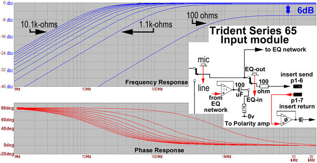
Figure 3: An exaggerated example of how excessive loading can reduce low frequencies (click for larger view).
Figure 3 depicts the insert points from a Trident Series 65 console. The “source” could be either the mic preamp or line input amp, pre- or post-equalizer, all determined by switches. In each case, the output op amp feeds a 100-micro-Farad (µF) capacitor and a 100-ohm resistor, much better choices for the application. (The Tascam circuit example was focused on R117 being too large to tolerate excessive cable capacitance. Note that the series capacitor in that circuit, C106, is 2.2µF.)
Micro-Cap’s simulation successfully shows what happens in a worst case scenario, the effect of excessive resistive loading of the 100µF output capacitor, creating a highpass (bass roll-off) filter. The very same filtering effect might occur if the output capacitor deteriorated, a very common ailment that plagues older equipment and discussed in last year’s column on “Upgrades and Maintenance Issues.”
The “load” ranged from an unlikely 100 ohms to the more typical 10.1 kil- ohms. Ignoring the 100-ohm load results for a moment, the Table details the frequencies that fall at the “-3dB” (half-power) point for each of the other load values.
Note: The internal 100-ohm resistor combined with the external 100-ohm load creates a 50% voltage divider, dropping the level 6 dB as indicated by the double arrow in Fig. 3.
FINALE
In Fig. 3, the lower graph depicts the simultaneous phase changes as the frequency is swept. Phase is one of the less tangible effects of filtering and equalization. Modern digital filters can be made sans phase shift. I have not had the opportunity to make a side-by-side comparison.
Though it has not been stated directly until now, you should walk away from this article knowing that a low-source impedance and a high-destination impedance are normal for transformerless gear. Even transformerless mic preamps have a 5-kilohm to 10-kil-ohm input impedance, some are variable. (Microphone impedance is typically 200 ohms.) Meanwhile, when interfacing transformer-based vintage (or retro) gear with modern technology, remember that the output transformer should be terminated, preferably at the destination. Speaking of which, at 2,500 words, I am outta here!
Home | Audio | DIY | Guitar | iPods | Music | Links | Site Map | Contact
![]()