|
|
Home | Audio | DIY | Guitar | iPods | Music | Brain/Problem Solving | Links| Site Map
This work is licensed under a Creative Commons License.
Balanced Cables and Audio
Balanced audio is a method of interconnecting audio equipment using impedance-balanced lines. This type of connection is very important in sound recording and production because it allows for the use of long cables while reducing susceptibility to external noise.
Balanced connections use three-conductor connectors, usually the XLR or TRS jack plug. XLR connectors, for instance, are usually used with microphones because of their durable construction, while TRS jack plugs are usually used for mixer inputs and outputs because of their smaller profile.
Applications
Many microphones operate at low voltage levels and some with high output impedance (hi-Z), which makes long microphone cables especially susceptible to electromagnetic interference. Microphone interconnections are therefore a perfect application for a balanced interconnection, which cancels out most of this induced outside noise.
If the power amplifiers of a public address system are located at any distance from the mixing console, it is also normal to use balanced lines for the signal paths from the mixer to these amplifiers. Many other components, such as graphic equalizers and effects units, have balanced inputs and outputs to allow this. In recording and for short cable runs in general, a compromise is necessary between the noise reduction given by balanced lines and the cost introduced by the extra circuitry they require.
Interference reduction
Balanced audio connections use a number of techniques to reduce noise.
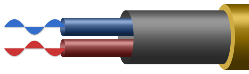
A typical balanced cable contains two identical wires, which are twisted together and then wrapped with a third conductor (foil or braid) that acts as a shield.
The term "balanced" comes from the method of connecting each wire to identical impedances at source and load. This means that much of the electromagnetic interference will induce an equal noise voltage in each wire. Since the amplifier at the far end measures the difference in voltage between the two signal lines, noise that is identical on both wires is rejected. The noise received in the second, inverted line is applied against the first, upright signal, and cancels it out when the two signals are subtracted.
This differential signal recombination can be implemented with a differential amplifier. A balun may also be used instead of an active differential amplifier device.
The wires are also twisted together, to reduce interference from electromagnetic induction. A twisted pair makes the loop area between the conductors as small as possible, and ensures that a magnetic field that passes equally through adjacent loops will induce equal levels of noise on both lines, which is canceled out by the differential amplifier. If the noise source is extemely close to the cable, then it is possible it will be induced on one of the lines more than the other, and it won't be canceled as well, but canceling will still occur to the extent of the amount of noise that is equal on both lines.
The separate shield of a balanced audio connection also yields a noise rejection advantage over an unbalanced two-conductor arrangement (such as used in typical home stereos) where the shield must also act as the signal return wire. Any noise currents induced into a balanced audio shield will not therefore be directly modulated onto the signal, whereas in a two-conductor system they will be. This also prevents ground loop problems, by separating the shield/chassis from signal ground.
Differential signalling
Signals are often transmitted over balanced connections using the differential mode, meaning the wires carry signals of opposite polarity to each other (for instance, in an XLR connector, pin 2 carries the signal with normal polarity, and pin 3 carries an inverted version of the same signal).
Despite popular belief, this is not necessary for noise rejection. As long as the impedances are balanced, noise will couple equally into the two wires (and be rejected by a differential amplifier), regardless of the signal that is present on them. A simple method of driving a balanced line is to inject the signal into the "hot" wire through a known source impedance, and connect the "cold" wire to ground through an identical impedance. Due to common misconceptions about differential signalling, this is often referred to as a quasi-balanced or impedance-balanced output, though it is, in fact, fully balanced and will reject common-mode interference.
There are some benefits to driving the line with a fully differential output, though:
- The electromagnetic field around a differential line is ideally zero, which reduces crosstalk into adjacent cables.
- Though the signal level would not be changed due to nominal level standardization, the maximum output from the differential drivers is twice as much, giving 6 dB extra headroom. (if the amplifiers are identical, though, their output noise sums to 3 dB more than a single amplifier, decreasing dynamic range).
- Noise that is correlated between the two amps (from poor power supply rejection, for instance), would be cancelled out.
- At higher frequencies, the output impedance of the output amplifier can change, resulting in a small imbalance. When driven in differential mode by two identical amplifiers, this impedance change will be the same for both lines, and thus cancelled out.
- Differential drivers are also more forgiving of incorrectly wired adapters or equipment that unbalances the signal by shorting pin 2.
Internally balanced audio design
Most professional audio products (recording, public address, etc.) provide differential balanced inputs and outputs, typically via XLR or TRS connectors. However, in most cases, a differential balanced input signal is internally converted to a single-ended signal via transformer or electronic amplifier. After internal processing, the single-ended signal is converted back to a differential balanced signal and fed to an output. A small number of professional audio products have been designed as an entirely differential balanced signal path from input to output; the audio signal never unbalances. This design is achieved by providing identical (mirrored) internal signal paths for both pin 2 and pin 3 signals (AKA "hot" and "cold" audio signals). In critical applications, a 100% differential balanced circuit design can offer better signal integrity by avoiding the extra amplifier stages or transformers required for front-end unbalancing and back-end rebalancing. Fully balanced internal circuitry has been promoted as yielding 3dB better dynamic range.
Home | Audio | DIY | Guitar | iPods | Music | Links | Site Map | Contact
![]()