Home | Audio | DIY | Guitar | iPods | Music | Brain/Problem Solving | Links| Site Map
This work is licensed under a Creative Commons License.
Below are the UNVERIFED connection diagrams used in the Bottlehead Foreplay III pre-amp. The 4PID-3 selector switch if from GoldPoint, as are the attenuators. You can use a 15K Goldpoint attenuator or use a GoldPoint Mini-V Custom and pack it with some Vishay-Dale, IRC, or other high-end resistors. Many listeners state that resistors provide a far superior listening experience than Goldpoint SMDs.


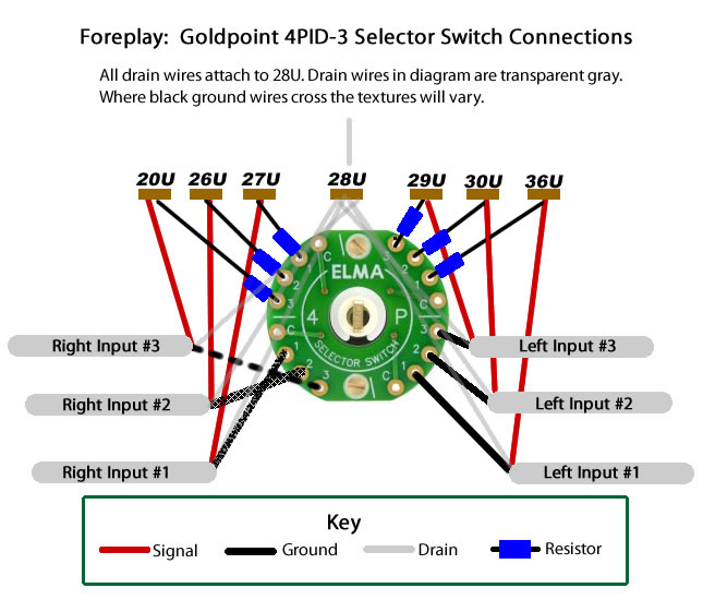
Goldpoint Selector Switch Model: 4P-3T-D [4 Poles (circuits), 3 Positions, 1 Deck] To avoid confusion I will use Quadrants instead of Poles when describing the diagrams. Our variables will be Q-Quadrant/Pole, and P for Position.
The 4P switch has 4 Quadrants, and they will be named Q1, Q2, Q3, and Q4 starting from the top and going clockwise/right. Each Circuit has 4 Positions (1, 2, 3, and C) and will be named P1, P2, P3, and Pc. We need now worry about the decks since we are using only one.
Before beginning, notice the order of the positions in each quadrant. For Q1 and Q2, the switch goes from 3, 2, 1, to c. For Q3 and A4 it is the opposite when reading from the top (c, 1, 2, and 3), but the same when reading clockwise 3, 2, 1, c).
Connecting the Switch
Quadrant I
Q1-P3 resistor goest to 29U
Q1-P2 resistor goest to 30U
Q1-P1 resistor goest to 36U
Q1-Pc nothing for nowQuadrant II
Left Input #3:
Q2-P3 black wire, red wire goes to 29U, and drain wire connects to 28ULeft Input #2:
Q2-P2 black wire, red wire goes to 30U, and drain wire connects to 28ULeft Input #3:
Q2-P1 black wire, red wire goes to 36U, and drain wire connects to 28U
Q2-Pc nothing for nowQuadrant III
Right Input #1:
Q3-P1 black wire, red wire goes to 20U, and drain wire connects to 28U
Right Input #2:
Q3-P2 black wire, red wire goes to 26U, and drain wire connects to 28U
Right Input #3:
Q2-P3 black wire, red wire goes to 27U, and drain wire connects to 28U
Q3-Pc nothing for nowQuadrant IV
Q4-P3 resistor goest to 20U
Q4-P2 resistor goest to 26U
Q4-P1 resistor goest to 27U
Q4-Pc nothing for nowConnecting Attenuators to Switch
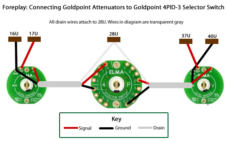
Right Channel Attenuator
Attenuator Ground connects to 16U and Attenuator In connects to 17U
Attenuator side: STP black connects to Attenuator ground and red to Attenuator out
Switch side: STP black connects to Q3-Pc, red connects to Q4-Pc, and drain connects to 28ULeft Channel Attenuator
Attenuator Ground connects to 37U and Attenuator In connects to 40U
Attenuator side: STP black connects to Attenuator ground and red to Attenuator out
Switch side: STP black connects to Q1-Pc, red connects to Q2-Pc, and drain connects to 28UPhotos
Note: All of the wiring was based on the diagrams above.
Above: Photo of Channel wires hooked-up but not yet soldered. It is far easier to do the work with only one attenuator in place. The drain wires have been covered with teflon tubing. IRC resistors are being used with the attenuators. Note: The STP cabeling is significantly larger than that that comes with the kit.
Above: Resistors have been covered with teflon tubing, and all connections have been soldered.
Above: Connecting the attenuators to the terminal strips.
Above: Stock STP was used to connect the attenuators to the switch.
Home | Audio | DIY | Guitar | iPods | Music | Links | Site Map | Contact